
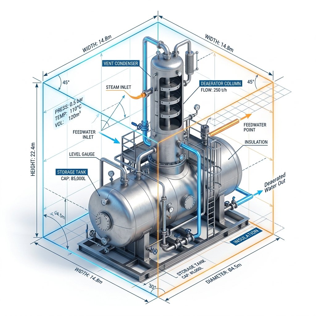
Proper boiler feed water tank sizing is one of the most critical aspects of thermal plant design. Whether acting as a simple hotwell or a pressurized deaerator storage section, the feed water tank serves as a massive thermal and hydraulic battery. It must store enough high-temperature, oxygen-scavenged water to respond immediately to severe spikes in steam demand without triggering a catastrophic low-water trip in the boiler drum.
In this comprehensive technical review, we will explore the thermodynamics of feed water storage, how to define the correct retention times for your specific industry, and the geometric formulas used to determine the exact physical dimensions (diameter and length) of the vessel. We will reference guidelines from the ASME BPVC Section VIII for pressure vessels and the American Boiler Manufacturers Association (ABMA).
If you are currently designing a feed system, you can use our automated boiler feed pump calculator to generate the required volumetric flow rates before moving on to the tank sizing equations below.
Understanding Retention Time Rules
The "retention time" (or storage capacity) of a boiler feed water tank dictates how many minutes the boiler can operate at its Maximum Continuous Rating (MCR) if the incoming makeup water or condensate return completely fails.
Selecting the appropriate retention time depends entirely on the application of the steam plant:
- Utility Power Plants (Base Load): Typically utilize 5 to 10 minutes of retention time. These plants have highly stable loads, massive condensate return systems, and highly automated redundant makeup water pumps.
- Industrial Process Plants: Typically require 10 to 20 minutes of retention time. Process plants (like paper mills or chemical refineries) often experience sudden, violent load swings and lose large amounts of steam to process heating.
- Critical Healthcare / Hospitals: May demand 20 to 30 minutes of retention time to guarantee absolute redundancy during a catastrophic municipal water failure.
Engineers must strike a balance. A tank that is sized too small will result in frequent low-level trips and severe thermal shocking of the boiler if cold makeup water rushes in. A tank that is sized too large wastes immense capital expenditure, occupies valuable plant real estate, and increases the structural load on the elevated steel platforms (required for NPSHa).
Calculating the Working Volume
Once the retention time (T_r) is selected based on ABMA guidelines or project specifications, we must calculate the required "Working Volume" of the tank. It is vital to note that the Working Volume is not the total physical volume of the steel vessel. The Working Volume is strictly the volume of water residing between the Low-Level Alarm (LLA) and the Normal Water Level (NWL) or High-Level Alarm (HLA).
- V_w = Working Volume required (m³ or Gallons)
- Q_volumetric = Total volumetric flow rate of the feed pump (m³/hr or GPH)
- T_r = Required retention time in minutes
As a practical rule of thumb in mechanical design, the Working Volume generally represents about 50% to 65% of the tank's Total Physical Volume. The remaining volume is occupied by the steam blanket (in a deaerator) and the dead space below the low-level alarm. Therefore, to estimate the Total Physical Volume of the vessel, engineers simply divide the Working Volume by 0.60.
This is deeply tied to the pump flow rate. If you haven't yet calculated your exact pump flow requirements, check out our guide on boiler feed pump calculation and sizing.
Geometric Sizing: The L/D Ratio
With the Total Physical Volume established, the next step is determining the physical geometry of the vessel. Feed water tanks and deaerators are almost universally designed as horizontal cylindrical pressure vessels with dished heads (ellipsoidal or torispherical).
The most critical geometric parameter is the Length-to-Diameter (L/D) ratio. For optimal manufacturing cost, material usage, and thermodynamic mixing, the L/D ratio of a horizontal feed tank should fall between 2.5 and 4.0.
Substitute L with (3 × D) to aim for a median L/D ratio of 3.0:
- D = Inside Diameter of the tank
- L = Tangent-to-Tangent Length of the tank
By solving this cubic equation, a mechanical engineer can quickly iterate to find the optimal Diameter (D). Once D is found, standardizing it to a readily available steel plate size or dished head mold will finalize the design.
The Impact of Tank Sizing on NPSHa
Finally, we must address the hydraulic integration between the tank and the boiler feed pump. Because deaerator tanks operate at saturation temperature, the vapor pressure of the water exactly equals the absolute pressure inside the tank.
This means the only energy keeping the water liquid at the pump impeller is the static elevation difference (Z) between the tank's Low-Level Alarm and the pump centerline. The physical size (Diameter) of the tank directly affects how high the water level fluctuates. A tank with a small diameter will see rapid drops in water elevation (Z) during high demand, which instantly destroys the Net Positive Suction Head Available (NPSHa) and triggers catastrophic pump cavitation.
To fully understand the destructive nature of cavitation and how to protect your pumps, read our definitive technical guide on NPSHa vs NPSHr for boiler systems.
Conclusion & Automated Tools
Boiler feed water tank sizing is not just about holding water; it is a complex balance of thermodynamic storage, mechanical pressure vessel design (ASME Section VIII), and hydraulic pump protection (API 610). By adhering to the 10-20 minute retention rules and maintaining optimal L/D geometries, engineers can guarantee decades of reliable steam plant operation.