
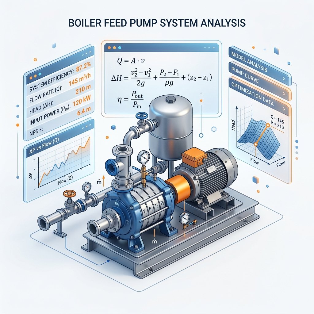
Performing an accurate boiler feed pump calculation is the foundational step in designing any resilient thermal steam plant. Whether you are engineering a high-pressure utility power station or a package boiler for food processing, the thermodynamic and hydraulic precision of your feed pump sizing will dictate the safety, efficiency, and lifespan of the entire operation.
In this comprehensive technical guide, we will break down the governing fluid mechanics equations, step-by-step sizing formulas, Total Dynamic Head (TDH) calculations, and rigorous Net Positive Suction Head (NPSH) evaluations necessary for industrial compliance. Our methodology strictly references global standards including the ASME Boiler and Pressure Vessel Code (BPVC) and API 610 guidelines.
If you want to instantly generate these figures without doing the manual math, you can use our free, automated boiler feed pump calculation tool directly on our homepage.
Determining Volumetric Flow Rate (Capacity)
Boilers are traditionally rated by their steam mass evaporation rate (e.g., kg/hr or lb/hr). However, centrifugal pumps operate purely on volumetric flow (e.g., m³/hr or Gallons Per Minute). Converting mass flow to volumetric flow requires understanding the specific gravity of water at the elevated temperatures found in a deaerator.
Furthermore, a feed pump cannot merely pump 100% of the boiler's steam rating. It must also overcome continuous blowdown losses and incorporate a safety margin to allow the boiler to recover from low-water level trips rapidly.
- M_total = Total feedwater mass flow
- M_steam = Boiler Maximum Continuous Rating (MCR)
- X_bd = Continuous blowdown fraction (typically 0.02 to 0.05)
- SF = Safety Factor (ASME recommends 1.15 to 1.25)
Once the total required mass flow is calculated, we divide it by the fluid density at the deaerator operating temperature. Water at 105°C (221°F) has a density of roughly 954 kg/m³, which is significantly less dense than cold water. Failing to adjust for thermal density is a common error that leads to heavily undersized pumps.
Calculating Total Dynamic Head (TDH)
Total Dynamic Head (TDH) represents the total equivalent height that a fluid is to be pumped, taking into account friction losses in the piping system. For a boiler feed pump calculation, the pump must overcome the internal operating pressure of the boiler drum, the static elevation difference, and the dynamic friction of the piping network.
- H_boiler = Boiler operating pressure converted to head (m or ft)
- H_static = Elevation difference between pump discharge and boiler inlet
- H_friction = Pressure drop through economizers, piping, and fittings
- H_control_valve = Minimum pressure drop required across the feedwater regulating valve
Often, the feedwater control valve represents the largest frictional pressure drop in the system. Control valve sizing requires a dedicated pressure differential (typically 10-15% of the system friction) to maintain adequate flow authority and prevent valve hunting during variable loads.
Cavitation & NPSHa Verification
A major aspect of any boiler feed pump calculation is guaranteeing that Net Positive Suction Head Available (NPSHa) comfortably exceeds the Net Positive Suction Head Required (NPSHr) by the pump manufacturer. If NPSHa falls below NPSHr, the hot feedwater will flash into steam inside the impeller eye. This phenomenon, known as cavitation, causes violent implosions that rapidly erode metal and destroy mechanical seals.
Because deaerators operate exactly at the saturation temperature of water, the fluid has zero subcooling. The vapor pressure (P_v) completely cancels out the surface pressure (P_da) in the deaerator. Therefore, the only physical force providing NPSHa is the static elevation (Z) of the deaerator above the pump suction centerline.
To learn more about optimizing this delicate balance and diagnosing cavitation issues, refer to our dedicated deep-dive on NPSHa vs NPSHr and cavitation prevention.
Boiler Feed Water Tank Sizing & Retention Rules
A feed pump is only as reliable as the reservoir supplying it. The boiler feed water tank (or deaerator storage section) must hold enough high-temperature water to act as a thermal buffer against sudden spikes in steam demand or interruptions in makeup water supply.
Standard thermal plant design practice mandates a 10 to 20 minute retention time for the feed tank. This implies that the tank's working volume (from the low-level alarm to the normal operating level) must be sufficient to supply the boiler at Maximum Continuous Rating for up to 20 minutes with zero incoming makeup water.
For a detailed walkthrough of the physical geometry, diameter-to-length ratios, and volume formulas, check out our complete Boiler Feed Water Tank Sizing Guide.
Conclusion: Automate Your Engineering Workflow
Manual boiler feed pump calculations require interpolating steam tables, tracking unit conversions across Imperial and Metric systems, and constantly referencing ASME safety margins. To eliminate human error and dramatically accelerate your design process, utilize our free online sizing engine.